MCU-Controlled Single-Button Power Switch Circuit with Schematic
This article presents an MCU-controlled single-button power switch circuit using a hardware-software hybrid approach. It employs a P-channel MOSFET (V1) as the main power switch, an N-channel MOSFET (V2) with MCU GPIO for state latching, and two diodes (D1, D2) for power-on control and shutdown detection. The circuit features simple structure, minimal components, low cost, and remote shutdown capability, suitable for 3.3V or 5V portable electronics.
Power on/off control is a fundamental and essential feature for electronic products. For MCU-based electronic devices, there are generally three approaches to implement system power switching:
I. Hard Switch Circuit
This typically uses mechanical switches with distinct "on/off" states, such as latching pushbutton switches, toggle switches, or slide switches, which directly control circuit continuity. The characteristics include simple design, high reliability, diverse options, and capability to handle high power loads. However, they tend to be bulky and less aesthetically pleasing. This is the traditional power switching method used in conventional electrical equipment.
II. Soft Switch Circuit
A soft switch consists of a mechanical button switch combined with a power on/off control circuit. In this scheme, the button switch does not directly control the power path or enable signal (when using LDOs or DC/DC converters with enable pins); instead, it merely provides a trigger signal to the control circuit. The power on/off control circuit is essentially a bistable circuit—the trigger signal from the button causes its output to toggle between high and low levels, thereby controlling the power path through a power stage to achieve system power switching. To enable power-on from a completely off state, the soft switch control circuit must remain in standby mode at all times.
The operating principle of soft switch circuits allows the use of compact, low-profile SMD pushbutton switches or inexpensive membrane switches, achieving "small controlling large" power switching that integrates well with panel designs for a sleek, modern appearance. This is commonly used in portable or consumer electronics requiring high aesthetic standards. However, the drawbacks are obvious: the circuit is relatively complex with many components; some circuits require continuous standby power, consuming energy that must be carefully considered for battery-powered portable devices.
III. Hardware-Software Hybrid Switch Circuit
This approach delegates part of the power switching and state retention functions to MCU software, using MCU GPIO signals with simple external circuitry to control power path switching and state retention. This achieves system power control with advantages including simple circuitry, few components, low cost, and flexible control. However, it requires coordinated hardware-software design, adding some complexity.
The MCU-controlled single-button power switch circuit presented below is such a hardware-software hybrid implementation. Its main circuit principles are as follows:
1. Circuit Composition
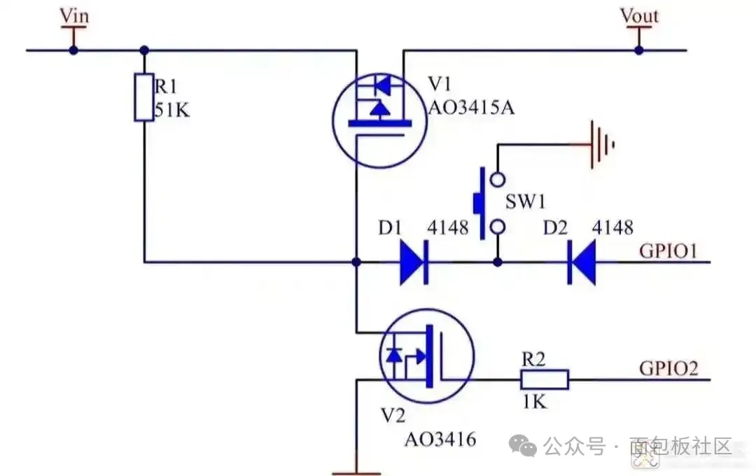
In the schematic:
- V1: P-channel MOSFET serving as high-side power switch
- Vin: Input power source
- Vout: Output power (load/MCU power supply)
- R1: Gate-source bias resistor for V1
- D1, D2: Diodes providing unidirectional signal control and detection—D1 works with SW1 for turn-on control, D2 works with SW1 for shutdown signal detection
- V2: N-channel MOSFET with gate resistor R2, forming an MCU-controlled low-side switch
- SW1: Mechanical button switch (can be standard pushbutton or membrane switch)
2. Operating States
Each press of the button cycles the system power state through: OFF → ON → OFF → ON → ...
3. Operation Sequence
① OFF State
Vin is powered, V1 is off, Vout is unpowered, GPIO1 and GPIO2 are low. SW1 is normally open, reverse-series diodes D1 and D2 are cut off, GPIO2 is low, N-channel MOSFET V2 is off. Since no current flows through R1, the gate-source voltage of P-channel MOSFET V1 is 0V, maintaining its off state. The system remains in stable shutdown condition.
② Power-On Sequence
When SW1 is pressed, the negative terminal of D1 is momentarily grounded, clamping V1's gate to approximately 0.7V. Current flows through R1, and the gate-source voltage of high-side switch V1 reaches -(Vin-0.7)V. When this exceeds the threshold voltage Vth, V1 turns on, powering Vout and starting the MCU. The software then sets GPIO2 to output high (configured as push-pull output), turning on V2 and pulling V1's gate near ground potential. Even after SW1 returns to open state, high-side switch V1 remains on through software control, maintaining stable system power-on state.
③ Power-Off Sequence
When the system is on and SW1 is pressed, MCU pin GPIO1 detects a negative edge through D2 (GPIO1 configured as input with weak pull-up enabled). The software detects this transition via polling or interrupt, interprets it as a valid shutdown signal, and switches GPIO2 from high to low output. NMOS V2 turns off, and with SW1 returning to open state, no current flows through R1. The gate-source voltage of high-side switch V1 becomes 0V, transitioning from on to off state. Load side Vout loses power, MCU stops operating, and the system returns to stable shutdown state.
From this operation sequence, it's evident that besides button-controlled shutdown, the system can also receive a "shutdown" signal through communication or other means to achieve remote power-off. This is a unique feature not available in other switch circuit types.
4. MOSFET Selection
Since MCU operating voltages are typically low (commonly 3.3V or 5V), MOSFET selection must carefully consider low-voltage switching characteristics to ensure reliable operation. Generally, high-performance small-signal enhancement-mode MOSFETs are recommended.
Share this article
Comments
0Please sign in to post a comment.
No comments yet.