Control GPIO Output: Light Up an LED on ESP32
This article demonstrates how to control ESP32 GPIO output to light up and blink an LED, providing a hands-on introduction to ESP32 hardware programming using Arduino.
Control GPIO Output: Light Up an LED on ESP32
Introduction
This tutorial explains how to control the GPIO output of an ESP32 to light up and blink an LED. It is designed for beginners to quickly get started with ESP32 hardware programming using the Arduino framework. By following this guide, you will understand the basic structure of an ESP32 program and gain confidence for future projects.
Principle of Operation
ESP32 GPIO Pins
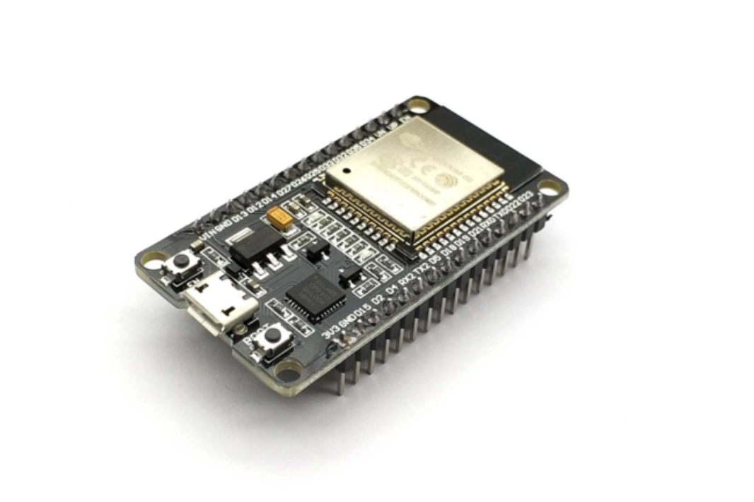
GPIO (General Purpose Input/Output) pins are the main interface for controlling external devices. On the ESP32 development board, pins labeled with D (such as D2, D4, D12, D15) are typical GPIOs. Each GPIO can be configured as input or output. In this guide, we focus on output mode to control an LED.
Voltage Levels:
- High level: Typically above 2.5V (for ESP32)
- Low level: Typically below 0.5V
These values may vary by board and should be verified in your hardware documentation.
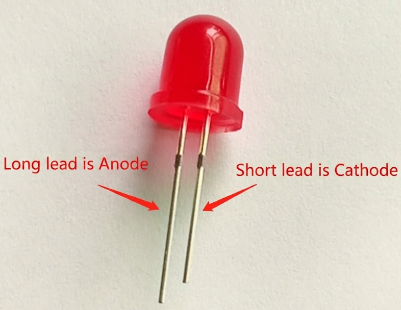
LED Basics
An LED (Light-Emitting Diode) emits light when current flows from its anode (long leg) to cathode (short leg). To prevent damage, always use a current-limiting resistor (typically 1kΩ) in series with the LED. The forward voltage drop is about 1.7V, and the recommended current is 3–20mA.
Hardware Setup
Bill of Materials (BOM):
| Item | Quantity |
|---|---|
| LED (through-hole) | 1 |
| 1kΩ resistor | 1 |
| Jumper wires | Several |
| Breadboard | 1 |
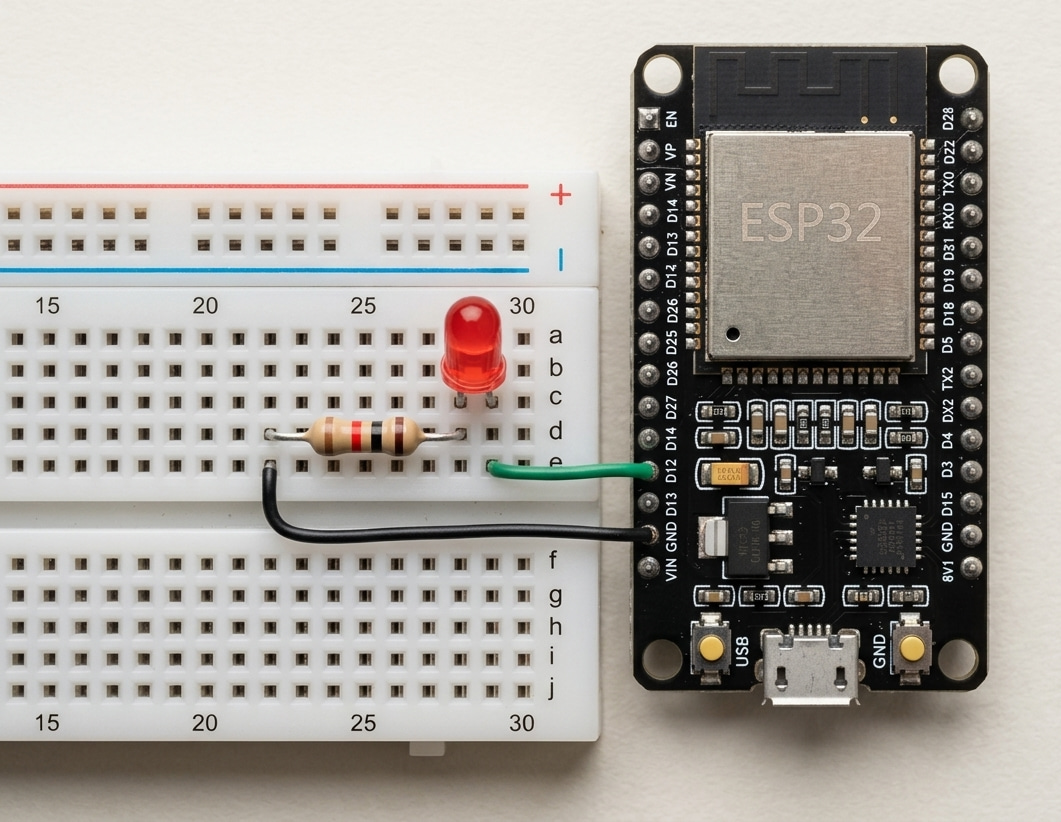
Wiring:
- Connect the LED anode (long leg) to ESP32 D12 via a 1kΩ resistor.
- Connect the LED cathode (short leg) to GND.
Warning: Always use a resistor in series with the LED to avoid excessive current and possible damage.
Software Design
Lighting Up the LED
To turn on the LED, set the corresponding GPIO pin as output and write a high level to it.
// Set the LED pin number
int led_pin = 12;

void setup() {
  // Configure the pin as output
  pinMode(led_pin, OUTPUT);
  // Turn the LED on
  digitalWrite(led_pin, HIGH);
}

void loop() {
  // Nothing to do here
}
Upload the code to your ESP32. The LED should light up.
Blinking the LED
To make the LED blink, toggle the pin state in the loop() function with a delay between on and off states.
// Set the LED pin number
int led_pin = 12;

void setup() {
  pinMode(led_pin, OUTPUT);
}

void loop() {
  // Turn the LED on
  digitalWrite(led_pin, HIGH);
  delay(1000); // Wait 1 second
  // Turn the LED off
  digitalWrite(led_pin, LOW);
  delay(1000); // Wait 1 second
}
Upload and run the program. The LED will blink at a 1-second interval.
References
Share this article
Comments
0Please sign in to post a comment.
No comments yet.