L298N DC Motor Driver Module Complete Guide
A complete guide to the L298N DC motor driver module, covering pin descriptions, power supply configurations, speed control with PWM, and wiring examples for use with Arduino or ESP32.
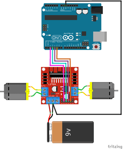
The L298N is one of the most popular dual H-bridge motor driver modules for controlling DC motors with a microcontroller like Arduino or ESP32. It can independently drive two DC motors in both directions, making it ideal for robotics and motor control projects.
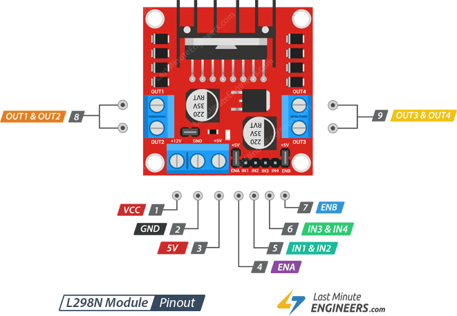
Pin Layout
The module can independently control two DC motors (Motor A and Motor B):
- IN1 & IN2 control Motor A
- IN3 & IN4 control Motor B
The direction of each motor is determined by the logic level of its two input pins:
| IN1 | IN2 | Motor A |
|---|---|---|
| HIGH | LOW | Forward |
| LOW | HIGH | Reverse |
| HIGH | HIGH | Stop |
| LOW | LOW | Stop |
In short: when the two inputs are at opposite levels, the motor runs; when both are the same level, the motor stops.
Pin Description
| Pin | Description |
|---|---|
| VCC | Motor power supply (5V–35V). If the 5V-EN jumper is in place, supply at least 2V more than the motor's rated voltage for maximum speed. |
| GND | Common ground. |
| 5V | Powers the L298N IC internal logic. Can supply 5V to external circuits when the 5V-EN jumper is installed. |
| OUT1 & OUT2 | Motor A output terminals. |
| OUT3 & OUT4 | Motor B output terminals. |
| IN1 & IN2 | Direction control for Motor A. |
| IN3 & IN4 | Direction control for Motor B. |
| ENA | Speed / enable control for Motor A. Pull HIGH (or keep jumper in place) to run; pull LOW to stop. Connect to a PWM pin to control speed. |
| ENB | Speed / enable control for Motor B. Same behavior as ENA. |
The board also has three jumpers:
- 5V EN — enables the onboard L78M05 voltage regulator
- 5V-ENA — ties ENA to 5V (motor A always enabled at full speed)
- 5V-ENB — ties ENB to 5V (motor B always enabled at full speed)
Understanding the 5V EN Jumper
The 5V EN jumper is the most commonly misunderstood part of this module. Here is the schematic for reference:
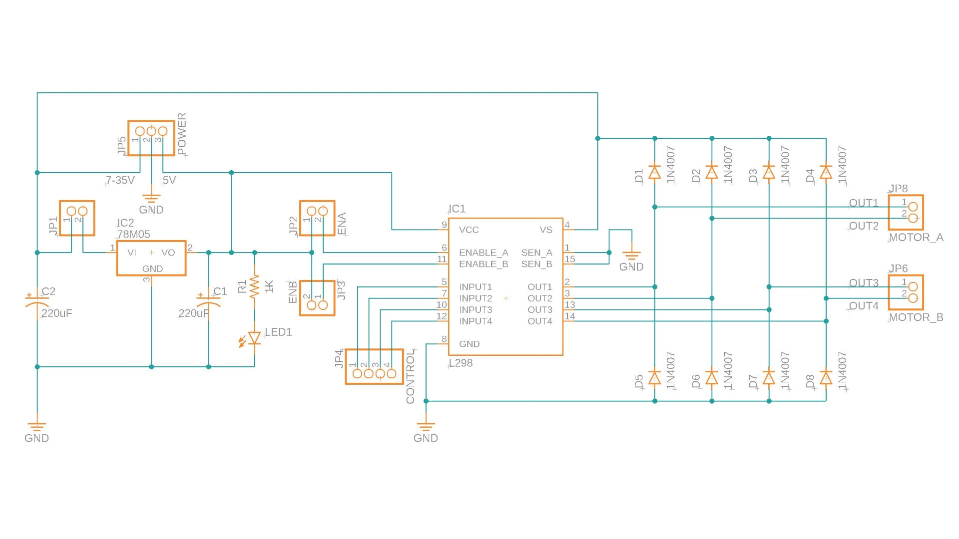
The L298N IC requires a 5V logic supply. The board includes an onboard L78M05 linear voltage regulator that steps down the motor supply voltage to 5V. The 5V EN jumper (JP1 in the schematic) connects the input power rail to the L78M05.
- Jumper installed — the L78M05 is powered, outputs 5V to both the L298N logic and the 5V output pin for external use.
- Jumper removed — the L78M05 is disabled; you must supply 5V externally to the 5V pin.
:::note The L78M05 has a 2V dropout voltage, which means the motor supply must be above 7V to produce a stable 5V output. :::
:::warning The L78M05 has a maximum input of 35V. If your motor supply exceeds 35V, remove the 5V EN jumper and power the 5V pin from an external regulated 5V source. :::
Power Supply Configurations
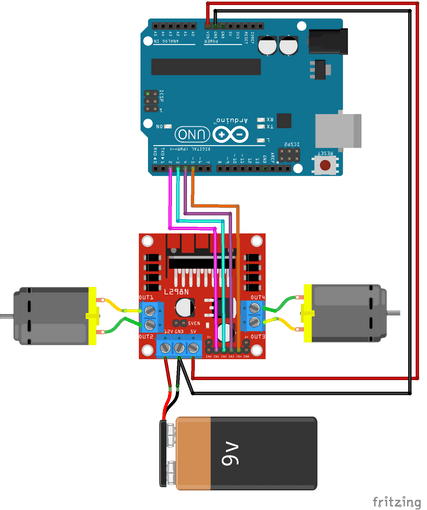
Option 1: L298N Powers Arduino
Use the 5V output of the L298N to power Arduino. This keeps things simple with fewer power sources.
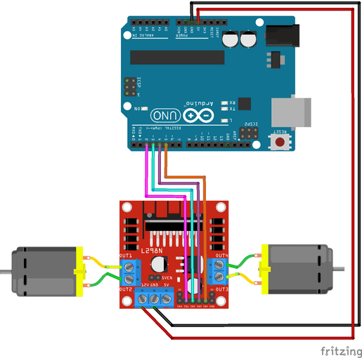
Option 2: Arduino Powers L298N
Arduino supplies 5V to the L298N logic input. This works for bench testing, but note that when Arduino is powered via USB, the motor supply voltage is only ~3V through the USB 5V rail, which may be insufficient to drive some motors.
Option 3: Separate Power Supplies
The cleanest solution for reliable motor operation — use a dedicated motor power supply and power Arduino independently.
:::tip Regardless of which power configuration you use, always connect Arduino GND and L298N GND together. :::
:::danger Never connect the L298N 5V output pin to an external 5V source at the same time. Two voltage sources fighting over the same rail can destroy both devices. :::
Example Code: Motor Direction Control
Wiring: Arduino powers L298N (Option 2 above).
int motor1pin1 = 2;
int motor1pin2 = 3;

int motor2pin1 = 4;
int motor2pin2 = 5;

void setup() {
  pinMode(motor1pin1, OUTPUT);
  pinMode(motor1pin2, OUTPUT);
  pinMode(motor2pin1, OUTPUT);
  pinMode(motor2pin2, OUTPUT);
}

void loop() {
  // Both motors forward
  digitalWrite(motor1pin1, HIGH);
  digitalWrite(motor1pin2, LOW);
  digitalWrite(motor2pin1, HIGH);
  digitalWrite(motor2pin2, LOW);
  delay(1000);

  // Both motors reverse
  digitalWrite(motor1pin1, LOW);
  digitalWrite(motor1pin2, HIGH);
  digitalWrite(motor2pin1, LOW);
  digitalWrite(motor2pin2, HIGH);
  delay(1000);
}
Speed Control with PWM (ENA / ENB Jumpers)
DC motor speed is proportional to the voltage supplied to it. PWM (Pulse Width Modulation) simulates variable voltage by rapidly switching the signal on and off — a higher duty cycle means more average voltage and a faster motor.
The L298N exposes this control through the ENA and ENB pins:
- ENA/ENB jumper installed — the enable pins are tied to 5V, so the motors always run at full power. No speed control is possible, but you save two wires.
- ENA/ENB jumper removed — connect these pins to PWM outputs on your Arduino/ESP32 to control speed programmatically.
// Set Motor A to ~20% of max speed (value range: 0–255)
analogWrite(ENA_pin, 50);
Share this article
Comments
0Please sign in to post a comment.
No comments yet.