
ESP32 4-Wire PT100/PT1000 High-Accuracy Temperature Measurement with MAX31865
Build a 4-wire PT100/PT1000 system with ESP32 and MAX31865. Learn why 4-wire RTD wiring removes lead resistance error and how to target about ±0.2°C with reference, layout, filtering, and calibration.
ESP32 4-Wire PT100/PT1000 High-Accuracy Temperature Measurement with MAX31865
In the previous article, I used the ESP32 ADC to read a PT1000 temperature sensor.
That approach is simple and works well for a basic temperature measurement project. However, if the goal is to build a temperature measurement system with better accuracy, the ESP32 internal ADC quickly becomes one of the limitations.
This is especially noticeable with a PT100 sensor.
A better approach is to separate the current-carrying wires from the voltage-sensing wires and use a dedicated RTD interface instead of the ESP32 ADC.
In this article, I will build a 4-wire PT100/PT1000 measurement circuit using the ESP32 and MAX31865.
A discrete precision ADC such as the ADS1220 can offer more analog flexibility, but the hardware design is more involved. I will cover that approach in a later article; here the focus is on a practical MAX31865-based system that is easier to wire and bring up on a prototype board.
The target is to build a system capable of reaching approximately ±0.2°C measurement accuracy under controlled conditions.
The actual accuracy depends on the RTD itself, reference resistor, excitation current, PCB layout, calibration and temperature environment.
Why use a 4-wire RTD?
There are several common ways to connect an RTD:
- 2-wire
- 3-wire
- 4-wire
The 2-wire connection is the simplest, but the resistance of the cable is included in the measurement.
This becomes a problem when the sensor is far away from the measurement circuit.
For example, a PT100 has a resistance of only 100 Ω at 0°C.
Its temperature coefficient is approximately:
Therefore, a resistance error of only:
corresponds to approximately:
This is a very small resistance.
The resistance of the connecting wires can easily become significant compared with this value.
A 4-wire connection solves this problem by using two wires to force the measurement current and two separate wires to measure the voltage.
The voltage measurement inputs draw almost no current, so the voltage drop caused by the sensor cable is largely removed from the resistance measurement.
This is why 4-wire measurement is commonly used when high RTD accuracy is required.
The MAX31865 documentation also describes the 4-wire configuration as eliminating cable-resistance error by separating the force and sense leads.
PT100 and PT1000
PT100 and PT1000 are platinum resistance temperature detectors.
The number indicates the nominal resistance at 0°C:
| Sensor | Resistance at 0°C |
|---|---|
| PT100 | 100 Ω |
| PT500 | 500 Ω |
| PT1000 | 1000 Ω |
For a standard platinum RTD, the resistance can be calculated using the Callendar-Van Dusen equation.
For temperatures above 0°C:
where:
- is the resistance at temperature
- is the resistance at 0°C
For temperatures below 0°C, the additional term is required.
The same equation was used in the previous PT1000 measurement article.
Why the ESP32 ADC is not enough
The internal ADC of the ESP32 is convenient, but it is not the best choice when the goal is a high-accuracy RTD measurement.
The previous circuit essentially looked like this:
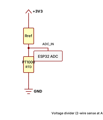
The ESP32 measures the voltage at the middle of the voltage divider and calculates the resistance.
This is easy to build, but several error sources appear:
- ADC offset
- ADC gain error
- ADC non-linearity
- supply voltage variation
- reference resistor tolerance
- electrical noise
- cable resistance
- PCB noise
- sensor self-heating
For a normal temperature display, these errors may not matter much.
For a ±0.2°C measurement system, they become important.
The solution is to move the precision analog measurement outside the ESP32.
The ESP32 can then concentrate on:
- SPI communication
- temperature calculation
- filtering
- data logging
- display
- Wi-Fi or Bluetooth communication
Using MAX31865
The MAX31865 is an RTD-to-digital converter designed specifically for platinum RTDs.
It integrates the pieces that are awkward to build by hand around a general-purpose ADC:
- PT100 / PT1000 / PT500 RTD support (configuration-dependent)
- 2-, 3-, and 4-wire RTD connections
- integrated excitation and ratiometric resistance measurement
- external precision reference resistor inputs
- 15-bit ADC
- SPI interface
- programmable 50 Hz / 60 Hz line-frequency rejection
For an ESP32 temperature project that needs a solid 4-wire RTD front end without designing a full analog signal chain, the MAX31865 is usually the better starting point than wiring the sensor straight to the MCU or rolling a custom ADC front end first.
The basic architecture becomes:
              PT100 / PT1000
             ┌──────────────┐
             │              │
Force + ─────┤              ├───── Force -
             │     RTD      │
Sense + ─────┤              ├───── Sense -
             │              │
             └──────────────┘
                │      │
                │      │
            MAX31865
           (RTD + REF)
                │
               SPI
                │
              ESP32
The important part is that the current path and voltage-sensing path are separated.
4-Wire PT100 connection
A 4-wire RTD has four terminals.
Two terminals are used for the excitation current:
I+
 |
 |
PT100
 |
 |
I-
The other two terminals measure the voltage directly across the RTD:
Sense+
   |
   +--------+
            |
          PT100
            |
   +--------+
   |
Sense-
Combining the two gives:
             PT100
        ┌──────────────┐
Force+ ─┤              ├─ Force-
        │              │
Sense+ ─┤              ├─ Sense-
        └──────────────┘
The voltage measured by the ADC is approximately:
Therefore:
Once the resistance is known, the resistance-to-temperature equation can be applied.
Why four wires improve the measurement
Consider a PT100 connected with a long cable.
Assume each cable has:
With a 2-wire connection, the measurement would see approximately:
Therefore:
For a PT100, 4 Ω corresponds to more than 10°C.
That is clearly unacceptable for precision temperature measurement.
With a 4-wire connection, the excitation current still flows through the cable, but the sense inputs measure the voltage directly across the RTD.
Because the ADC input current is extremely small, the voltage drop caused by the sense wires is negligible.
This is the main advantage of the 4-wire configuration.
Choosing the excitation current
The excitation current is an important design parameter.
A higher current produces a larger voltage across the RTD:
which improves the signal level.
However, the RTD also dissipates power:
This causes self-heating.
For example, with a PT100 at approximately 100 Ω:
500 µA
1 mA
Therefore, using a relatively small excitation current is usually preferable when the sensor itself must not heat significantly.
On a MAX31865 module, excitation is set by the reference resistor and the chip’s ratiometric topology rather than by manually tuning a current source register. Typical PT100 breakouts populate a 430 Ω reference, which is a common starting point in Maxim’s reference designs.
When you design your own PCB, choose the reference resistor and RTD wiring mode to match the datasheet and your sensor type. If self-heating is a concern, prefer a lower effective excitation (appropriate reference value and filtering) over chasing the largest possible ADC code swing.
PT100 voltage level
With a 500 µA excitation current:
At 0°C:
therefore:
At 100°C, PT100 resistance is approximately 138.5 Ω:
This is a relatively small voltage.
This is exactly why a dedicated RTD interface is useful: the MAX31865 measures RTD resistance ratiometrically against the reference resistor, so the ESP32 does not need to digitize these millivolt-level signals directly.
PT1000 is easier to measure
A PT1000 produces ten times the resistance of a PT100.
At 0°C:
With 500 µA excitation:
The signal is therefore much larger than the PT100 signal.
This is one reason PT1000 can be attractive when the application allows it.
However, the sensor specification, physical size, response time and self-heating still need to be considered.
Ratiometric measurement
For a precision design, the reference voltage is just as important as the ADC resolution.
The MAX31865 is built around a ratiometric measurement.
Instead of relying on an absolutely accurate excitation voltage, the RTD voltage and ADC reference are derived from the same current source.
Conceptually:
             Excitation Current
                    |
                    |
                  RTD
                    |
                    |
                   GND

             Reference Resistor
                    |
                    |
                   GND
The ADC compares the RTD voltage with the reference voltage.
If the excitation current changes slightly, both voltages change together.
A large part of the excitation-current error therefore cancels.
This is one of the reasons precision RTD interfaces often use ratiometric measurements.
Reference resistor
The reference resistor is another important component.
For a precision system, do not use an ordinary 1% resistor.
A better choice is a precision resistor with:
- low initial tolerance
- low temperature coefficient
- good long-term stability
For example:
0.1% tolerance
10 ppm/°C or better
would be a reasonable starting point.
On many MAX31865 breakout boards, this resistor is already on the module (often 430 Ω for PT100-centric designs). On a custom PCB, place the reference next to the chip, match the value to your RTD type per the MAX31865 datasheet, and keep the REF traces short and away from noisy digital routing.
Converting resistance to temperature
Once the MAX31865 reading gives the RTD resistance (many Arduino libraries expose readRTD() and optional linearized temperature), the ESP32 can calculate the temperature explicitly if you prefer full control over the conversion equation.
For temperatures above 0°C:
float calculateTemperature(float resistance, float r0)
{
    const float A = 3.9083e-3;
    const float B = -5.775e-7;

    float a = B * r0;
    float b = A * r0;
    float c = r0 - resistance;

    return (-b + sqrt(b * b - 4.0 * a * c)) / (2.0 * a);
}
For example, for a PT100:
float temperature = calculateTemperature(resistance, 100.0);
For a PT1000:
float temperature = calculateTemperature(resistance, 1000.0);
For a wider temperature range, especially below 0°C, the complete Callendar-Van Dusen equation should be used.
ESP32 and MAX31865
The MAX31865 communicates with the ESP32 through SPI.
A typical connection to a 3.3 V breakout module is:
ESP32              MAX31865 module
3.3V       ------> VIN
GND        ------> GND
GPIO18     ------> CLK
GPIO19     <------ SDO (MISO)
GPIO23     ------> SDI (MOSI)
GPIO5      ------> CS
The exact GPIO assignment is not important as long as the SPI pins, level, and chip-select line match your sketch.
The important point is to keep the analog section physically separated from noisy digital circuitry.
For example:
+---------------------------------------+
|                                       |
|  PT100 connector                      |
|       │                               |
|       │                               |
|  (optional analog filter on custom PCB)|
|       │                               |
|       ▼                               |
|    MAX31865                           |
|       │                               |
|       │ SPI                           |
|       ▼                               |
|    ESP32                              |
|                                       |
|                     Wi-Fi antenna     |
+---------------------------------------+
Keep the RTD input traces away from:
- ESP32 antenna
- switching regulators
- DC/DC inductors
- high-speed SPI traces
- relay drivers
- motors
This matters more than simply increasing the ADC bit count.
Filtering the RTD signal
RTD measurements do not normally need a high sampling rate.
Temperature changes relatively slowly.
For example, there is little reason to measure a temperature sensor at several thousand samples per second in a normal monitoring application.
A lower data rate allows the ADC's digital filtering to remove more noise.
For example:
RTD
 ↓
MAX31865 (line-frequency filter enabled)
 ↓
SPI read
 ↓
Software averaging
 ↓
Temperature
The MAX31865 can reject 50 Hz or 60 Hz interference when configured appropriately, which helps when sensor wiring runs near mains-powered equipment. On a custom PCB you may still add a small RC filter at the RTD inputs; many ready-made modules rely on the chip’s digital filtering plus careful layout.
Moving average
After obtaining the temperature from the ADC, a simple moving average can be applied.
For example:
#define FILTER_SIZE 16

float temperatureBuffer[FILTER_SIZE];
int filterIndex = 0;

float filterTemperature(float value)
{
    temperatureBuffer[filterIndex] = value;

    filterIndex++;
    if (filterIndex >= FILTER_SIZE)
        filterIndex = 0;

    float sum = 0;

    for (int i = 0; i < FILTER_SIZE; i++)
        sum += temperatureBuffer[i];

    return sum / FILTER_SIZE;
}
This does not improve the fundamental accuracy of the RTD.
It reduces random measurement noise.
That distinction is important.
If the sensor has a systematic error of +0.5°C, averaging 100 measurements will not turn it into a ±0.2°C sensor.
What is required for ±0.2°C?
Using a dedicated RTD converter does not automatically mean that the final temperature accuracy will be ±0.2°C.
The complete error budget has to be considered.
A practical system needs to consider:
| Error source | Importance |
|---|---|
| RTD accuracy | Very high |
| RTD calibration | Very high |
| Lead resistance | 4-wire largely eliminates this |
| Reference resistor | High |
| Excitation current | High |
| ADC offset | High |
| ADC noise | Medium |
| PCB leakage/noise | Medium |
| Self-heating | Medium |
| Thermal gradient | High |
| Temperature conversion | Low with correct equation |
For example, if the RTD itself has a large tolerance, replacing the ADC will not solve the problem.
The sensor needs to be specified appropriately.
For applications where ±0.2°C is important, it is also worth calibrating the complete measurement chain rather than relying only on nominal component specifications.
A simple calibration method
A practical way to improve the final result is to calibrate the complete system at one or more known temperatures.
For example:
Measurement system
        |
        ▼
Reference temperature
        |
        ▼
Measure RTD
        |
        ▼
Calculate error
        |
        ▼
Store calibration coefficient
        |
        ▼
Apply correction
A single-point calibration can remove a large offset.
For example, if the reference temperature is:
25.00°C
and the system reports:
25.18°C
the correction offset would be approximately:
-0.18°C
For a wider temperature range, two-point calibration is better.
For example:
0°C reference
25°C reference
or:
0°C reference
50°C reference
The measured points can then be used to calculate both offset and gain correction.
Do not ignore the sensor itself
There is an important difference between:
ADC resolution
and
system accuracy.
A 15-bit RTD ADC gives useful digital resolution, but that does not mean the temperature measurement is accurate to 0.001°C.
The actual result is limited by the complete measurement chain.
For example:
MAX31865 + precision reference
      ↓
Stable excitation / ratiometric measurement
      ↓
4-wire connection
      ↓
Precision RTD
      ↓
Good PCB layout
      ↓
Calibration
      ↓
±0.2°C system
The entire chain has to work together.
Why MAX31865 here (ADS1220 later)
This article centers on the MAX31865 because it is an RTD-specific front end: excitation, reference, and conversion are integrated, and breakout modules are widely available. That keeps the first high-accuracy ESP32 RTD build approachable.
The ADS1220 remains a strong choice when you need a general-purpose precision delta-sigma ADC (programmable gain, multiple channels, custom topologies, or sensors beyond platinum RTDs). Those designs usually need more analog engineering—reference layout, IDAC routing, input filtering, and register tuning—which is why a follow-up article will treat the ADS1220 path separately.
| Goal | Practical starting point |
|---|---|
| 4-wire PT100/PT1000 on ESP32, fast bring-up | MAX31865 (this article) |
| Custom RTD analog chain, multi-sensor ADC | ADS1220 (planned follow-up) |
Final circuit architecture
For a precision ESP32 temperature measurement project, my preferred architecture would be:
        PT100 / PT1000
          4 wires
             │
             ▼
     ┌─────────────────┐
     │ Analog filtering│
     └────────┬────────┘
              │
              ▼
     ┌─────────────────┐
     │   MAX31865      │
     │                 │
     │  RTD inputs     │
     │  REF resistor   │
     │  15-bit ADC     │
     └────────┬────────┘
              │
             SPI
              │
              ▼
     ┌─────────────────┐
     │      ESP32      │
     │                 │
     │ Resistance      │
     │       ↓         │
     │ Temperature     │
     │       ↓         │
     │ Filtering       │
     │       ↓         │
     │ Display / Wi-Fi │
     └─────────────────┘
This architecture is considerably more robust than connecting the RTD directly to an ESP32 ADC.
Conclusion
The ESP32 internal ADC is sufficient for a basic PT100/PT1000 experiment, but it is not the first choice when the goal is a stable high-accuracy temperature measurement.
A 4-wire RTD connection removes one of the major sources of error: lead resistance.
Adding a MAX31865 provides a much better RTD front end than the ESP32 ADC alone, including 4-wire support, ratiometric measurement, reference inputs, and line-frequency filtering options.
With:
- a suitable PT100/PT1000 sensor
- 4-wire connection
- a quality reference resistor (on-module or on your PCB)
- appropriate SPI wiring and software filtering
- good PCB layout
- calibration
a measurement system around the ±0.2°C level becomes a realistic engineering target.
It is important, however, to treat ±0.2°C as a system-level target rather than a guaranteed result from the converter alone.
The next step is to wire a MAX31865 module in 4-wire mode, read stable resistance or temperature values over SPI, and verify the error against a calibrated reference thermometer. When you outgrow the integrated RTD IC, the ADS1220-based design article will cover a more flexible—but more complex—analog path.
Related articles
Share this article
Comments
0Please sign in to post a comment.
No comments yet.