Author: southcreek | Source: Breadboard Community
1. Low-Speed Signal Conditioning (Slowly Varying Signals)
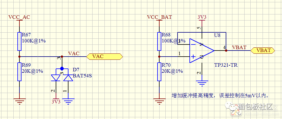
When measuring slow-changing signals such as NTC temperature sensors or power supply voltages using an MCU's internal ADC, cost-effective methods are usually sufficient.
- Resistive Voltage Dividers: A simple resistor divider can often meet basic requirements.
- Impedance Consideration: The output impedance of the divider is approximately the parallel resistance of the two resistors. For example, a divider using and resistors has an output impedance of roughly .
- Accuracy Tip: Since the ADC's input impedance is finite, you may need to reduce the sampling rate to increase the effective input impedance and maintain accuracy.
- Buffer Amplifiers: For higher precision, an Operational Amplifier (Op-Amp) can be used as a buffer (Voltage Follower) to provide low output impedance.* Key Parameter: Pay attention to the Input Offset Voltage (). In a follower configuration, the output is . While standard Op-Amps like the LM358 or LM324 have a around , high-precision Op-Amps should be used if tighter accuracy is required.
2. High-Speed Signal Conditioning (Fast Varying Signals)
Most MCU ADCs have sampling rates between 1 to 2 MSPS, meaning they can effectively process signals in the 500kHz to 1MHz range according to the Nyquist sampling theorem.
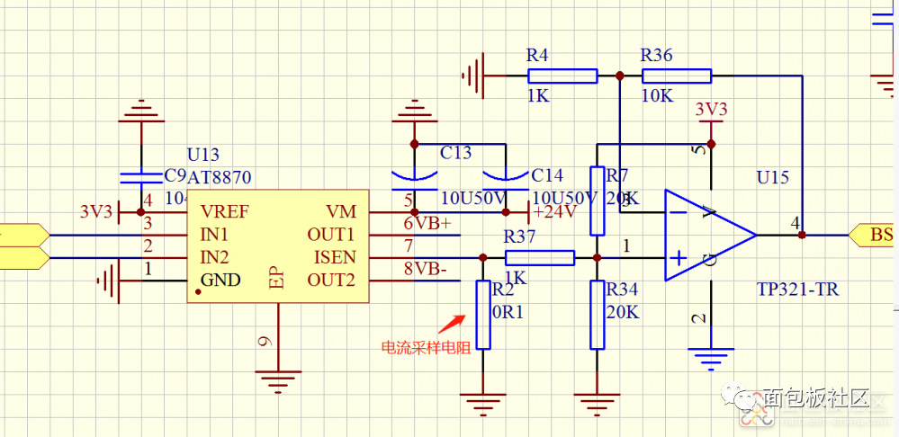
- Case Study: Motor Current Sensing: When measuring current across a shunt resistor (), the resulting voltage may be negative. An amplifier is used to offset the signal to a center-point (bias) for the ADC to read.
- Critical Op-Amp Parameters: For fast signals, is less critical (as it can be calibrated out by measuring the zero-input offset), but two other factors become vital:
- Gain Bandwidth Product (GBWP): If an Op-Amp has a GBWP of and a gain of 10 is applied, the effective bandwidth drops to only 100kHz.
- Slew Rate (SR): This determines how fast the output can change.
3. Analysis of Signal Distortion
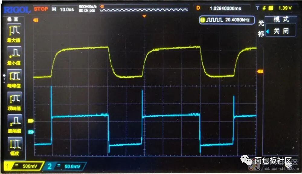
The author highlights that weak, millivolt-level signals with steep edges suffer significant distortion when amplified by a factor of 10 using a standard Op-Amp (like the LM321).
- The Problem: Due to limited GBWP and SR (e.g., ), the rising and falling edges of the amplified signal become "sluggish" or rounded.
- Observation: If the gain is halved, the edges become noticeably faster, confirming that the amplifier's limits are being reached.
4. Component Selection
To resolve waveform distortion in high-speed applications, specialized Op-Amps are required:
- Recommended Specs: Low-noise Op-Amps (e.g., RS821 or RS721) featuring:
- GBWP:
- Slew Rate:
Conclusion
Different signal types demand different Op-Amp specifications. While the LM358 is a versatile classic, it is not a "one-size-fits-all" solution for high-speed or high-precision sensing.
Share this article
Comments
0Please sign in to post a comment.
No comments yet.