PCF8574 I2C GPIO Expander with ESP32: Complete Guide
Running out of GPIO pins on your ESP32? This guide shows you how to use the PCF8574 I2C GPIO expander to add up to 64 extra I/O pins via a two-wire bus, covering wiring, address config, LED control, button input, interrupts, and matrix keypads.
PCF8574 GPIO Expansion for ESP32 (Quick Guide)
Need more GPIO on ESP32 without changing the MCU? PCF8574 is a low-cost I2C expander that adds 8 digital I/O pins per chip, up to 64 pins with 8 addresses.
This short guide covers only the essentials: when to use it, how to wire it, and the minimum code to get it working.
When PCF8574 Is the Right Choice
Use it for low-speed digital tasks:
- LEDs
- Buttons
- Relays
- Matrix keypads
Avoid it for timing-critical outputs such as high-speed PWM.
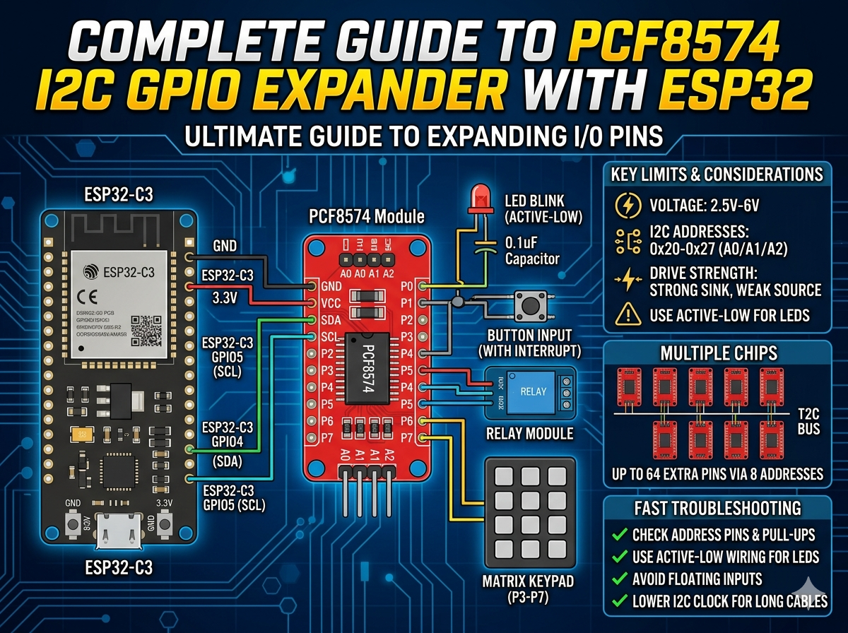
Key Limits You Must Remember
- Voltage: 2.5V to 6V
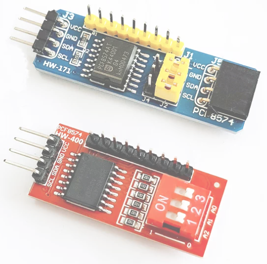
- I2C addresses: 0x20 to 0x27 (A0/A1/A2)
- Pins: 8 quasi-bidirectional GPIO
- Strong sink current, weak source current
Practical rule: drive LEDs in active-low mode.
Wiring with ESP32-C3
Example pin map:
PCF8574 -> ESP32-C3
VCC     -> 3.3V
GND     -> GND
SDA     -> GPIO4
SCL     -> GPIO5
A0/A1/A2 -> GND/GND/GND (0x20)
Make sure SDA and SCL have pull-up resistors (often already on the module).
Library Setup
PlatformIO:
lib_deps = RobTillaart/PCF8574@^0.2.1
Minimal Code: Scan + Blink
First scan I2C to confirm the address, then blink an LED on P0.
#include <Arduino.h>
#include <Wire.h>
#include <PCF8574.h>

PCF8574 pcf(0x20);

void scanI2C() {
  Serial.println("I2C scan:");
  for (uint8_t addr = 1; addr < 127; addr++) {
    Wire.beginTransmission(addr);
    if (Wire.endTransmission() == 0) {
      Serial.print("Found: 0x");
      if (addr < 16) Serial.print('0');
      Serial.println(addr, HEX);
    }
  }
}

void setup() {
  Serial.begin(115200);
  Wire.begin(4, 5, 400000);
  scanI2C();

  if (!pcf.begin()) {
    Serial.println("PCF8574 init failed");
    while (true) delay(1000);
  }
}

void loop() {
  pcf.digitalWrite(0, LOW);   // LED ON (active-low)
  delay(500);
  pcf.digitalWrite(0, HIGH);  // LED OFF
  delay(500);
}
Input and Interrupt Notes
- For input behavior, write HIGH before reading a pin.
- For buttons, connect the button to GND (pressed = LOW).
- Use INT pin if you want event-driven input instead of polling.
Multi-Chip Expansion
Set A0/A1/A2 differently per board to use 0x20 to 0x27. One bus can control 8 chips.
If communication becomes unstable, reduce I2C speed to 100kHz and shorten wiring.
Fast Troubleshooting
- No device found: check address pins, SDA/SCL swap, pull-ups.
- LED not lighting: use active-low wiring.
- Random input reads: avoid floating input, improve wiring and grounding.
- Occasional bus errors: lower clock rate and reduce cable length.
Takeaway
PCF8574 is one of the simplest ways to expand ESP32 GPIO for low-speed control. If you follow active-low output wiring, proper I2C pull-ups, and correct address setup, it is reliable and easy to scale.
Share this article
Comments
0Please sign in to post a comment.
No comments yet.