ESP32 GPIO Pitfalls: 3 Critical Mistakes That Break Real Projects
This guide explains three high-impact ESP32 GPIO pitfalls, including restricted pins, floating inputs, and unstable reset design, with practical ESP-IDF code and hardware rules you can apply immediately.
Many ESP32 bugs look like software failures, but the root cause is often GPIO configuration or board wiring. If your LED does not toggle, your key input is random, or your board restarts unexpectedly, GPIO rules are usually the first thing to verify.
This article focuses on three critical pitfalls that cause most early ESP32 bring-up problems. You will get pin selection rules, stable input design, and production-ready ESP-IDF examples.
Assumption: this article targets classic ESP32 modules such as ESP32-WROOM-32E and ESP-IDF v5.x. Some pin behavior differs on ESP32-S2/S3/C3 families.
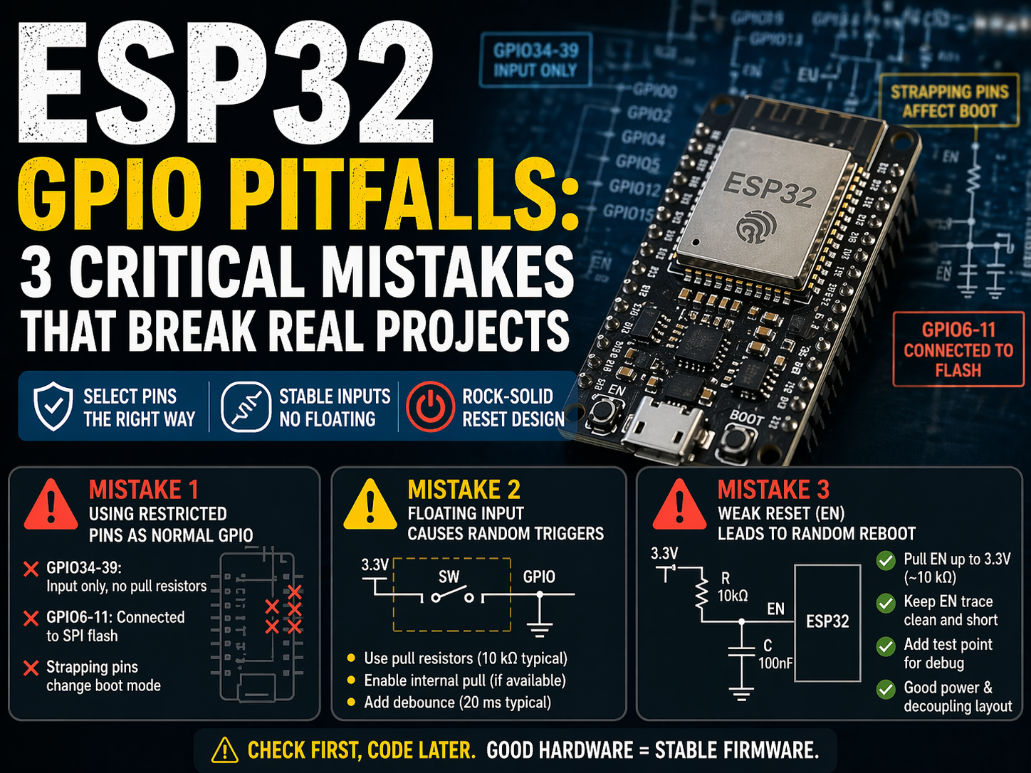
Pitfall 1: Using restricted pins as normal GPIO
Conclusion: not every ESP32 pin is general-purpose in real products.
Key constraints on classic ESP32:
| Pin group | Practical limitation | Typical failure |
|---|---|---|
| GPIO34-39 | Input only, no output driver | LED or relay output never works |
| GPIO34-39 | No internal pull-up or pull-down | Button input floats if no external resistor |
| GPIO6-11 | Connected to SPI flash on most modules | Boot crash or random reset if repurposed |
| Strapping pins (GPIO0, 2, 4, 5, 12, 15) | Affect boot mode and voltage config | Board fails to boot after wiring changes |
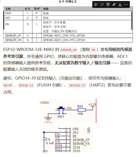
Important correction: GPIO36 (SENSOR_VP) and GPIO39 (SENSOR_VN) can be used as input pins, but they are input-only and do not support internal pull resistors. They are not valid output pins.
Pitfall 2: Floating input design causes random triggers
Conclusion: an un-driven input line is an antenna, not a valid logic signal.
A common error is enabling input mode without a stable pull resistor. This creates random level flips from EMI and board noise.
Wrong pattern:
gpio_config_t btn_conf = {
    .pin_bit_mask = (1ULL << GPIO_NUM_25),
    .mode = GPIO_MODE_INPUT,
    .pull_up_en = GPIO_PULLUP_DISABLE,
    .pull_down_en = GPIO_PULLDOWN_DISABLE,
    .intr_type = GPIO_INTR_DISABLE,
};
gpio_config(&btn_conf);
Recommended strategy:
- Use a hardware pull-up or pull-down resistor (10 kOhm is a common starting point).
- If the selected pin supports it, also enable internal pull as secondary protection.
- Add debounce in software or hardware.
Debounce example:
if (gpio_get_level(GPIO_NUM_25) == 0) {
    vTaskDelay(pdMS_TO_TICKS(20));
    if (gpio_get_level(GPIO_NUM_25) == 0) {
        // confirmed key press
    }
}
Pitfall 3: Weak reset (EN) design leads to random reboot
Conclusion: unstable EN wiring can look like firmware instability.
Board-level reset recommendations:
- Pull EN up to 3.3 V with about 10 kOhm.
- Keep EN trace away from noisy switching power nodes.
- Add a reset test point for production debug.
- Keep the power rail and decoupling layout clean near the module.
If EN is noise-sensitive, the board may restart under Wi-Fi transmit peaks or motor load transients, even with correct firmware.
ESP-IDF templates you can reuse
Conclusion: standardize GPIO init functions early to avoid repeated mistakes.
Reliable output init
#include "driver/gpio.h"
#include "esp_err.h"

esp_err_t led_init(gpio_num_t led_pin)
{
    gpio_config_t io_conf = {
        .pin_bit_mask = (1ULL << led_pin),
        .mode = GPIO_MODE_OUTPUT,
        .pull_up_en = GPIO_PULLUP_DISABLE,
        .pull_down_en = GPIO_PULLDOWN_DISABLE,
        .intr_type = GPIO_INTR_DISABLE,
    };
    return gpio_config(&io_conf);
}
Reliable input with interrupt
#include "driver/gpio.h"
#include "esp_attr.h"
#include "esp_err.h"

#define BUTTON_PIN GPIO_NUM_25

static void IRAM_ATTR button_isr(void *arg)
{
    (void)arg;
    // keep ISR short, defer work to task/queue
}

esp_err_t button_init(void)
{
    gpio_config_t btn_conf = {
        .pin_bit_mask = (1ULL << BUTTON_PIN),
        .mode = GPIO_MODE_INPUT,
        .pull_up_en = GPIO_PULLUP_ENABLE,
        .pull_down_en = GPIO_PULLDOWN_DISABLE,
        .intr_type = GPIO_INTR_NEGEDGE,
    };
    ESP_ERROR_CHECK(gpio_config(&btn_conf));
    ESP_ERROR_CHECK(gpio_install_isr_service(0));
    ESP_ERROR_CHECK(gpio_isr_handler_add(BUTTON_PIN, button_isr, NULL));
    return ESP_OK;
}
Engineer checklist before you blame firmware
Conclusion: this quick checklist prevents most GPIO bring-up failures.
- Verify selected pins against module restrictions.
- Avoid GPIO6-11 on flash-based ESP32 modules.
- Do not use GPIO34-39 for output.
- Remember GPIO34-39 have no internal pull resistors.
- Validate strapping pin levels during reset.
- Add pull resistors and debounce for every mechanical key input.
- Verify EN pull-up and noise immunity on the PCB.
Final takeaway
ESP32 GPIO is reliable when hardware constraints are respected. Most failures come from invalid pin assumptions, floating inputs, or weak reset design, not from complex software bugs.
If you apply the pin rules and templates in this article, your first-pass bring-up success rate will improve significantly.
References
- Espressif, ESP32 Series Datasheet
- Espressif, ESP-IDF Programming Guide, GPIO Driver
- Espressif, Hardware Design Guidelines for ESP32
Share this article
Comments
0Please sign in to post a comment.
No comments yet.